7.5.9 IPC 使用指南
此章节着重说明 MCU 侧的相关使用说明,更多的 IPC 的原理和使用可以查阅 IPC模块介绍 章节。
使用限制说明
- 在��使用 Ipc_MDMA_SendMsg 接口发送数据时, 需要保证数据 buffer 地址16字节对齐。
- 发送功能通过轮询方式查看 dma 状态,因此使用发送功能前必须关闭 DMA 中断(释放的代码默认已关闭);使用接收功能时,DMA 中断和 IPC 中断配置成相同的优先级,避免相互打断。
- Ipc Mdma 发送通道只有两个,单核或多核多任务发送时,建议使用自旋锁或者关中断方式控制 DMA 资源抢占。
- IPC 多核发送或接收基于 Instance 分配,不支持基于 Channel 分配。
- IPC 初始化需要在 DMA 模块初始化后再调用。
- MCU IPC 配置需要核对端 IPC 配置保持一致。包括 Instance 控制段与 data 段地址,Channel 的数量与 ID,Buffer 数据,Buffer 大小,两端配置不一致会导致 IPC 通信失败。
- Instance cfg 中的 receive_coreid 配置,需要明确该 Instance 是工作在 MCU0还是 MCU1,工作在 MCU1即配置为 Ipc_Receive_Core1,该项配置错误会导致 IPC 通信失败。
- Instance 工作在哪个 MCU 上,IPC 中断即在哪个 MCU 上进行使能。如果在多核上都使能,可能出现中断被其他核抢占导致 IPC 通信失败。
IPC 配置相关
一个 IPC 实例有一个或多个 channel,同一个实例共享一个中断,因此一个 IPC 只能在 MCU0或 MCU1其中一个系统上使能。
当 MCU1使用 IPC 时,需要配置两部分内容。
- 需要配置回调函数,作用是 IPC 接收到 notify 信号时触发中断进入回调函数进行处理。当然客户可自行定制当传输数据错误时的回调函数。下文以 Instance0为例介绍。
static Ipc_ChannelConfigType Ipc_ShmInstance0CfgChannel[8] = {
{
    .ChannelId = 0,
    .ChannelData   = {
        .NumPools = 1,
        .PoolCfg        = Ipc_ShmIpcInstance_0CfgIpcChannel_0BufPool,
        .RxCallback     = IpcTp_InsCan_RxCallback,
        .RxCallbackArg  = (NULL_PTR),
        .TxErrCallback    = DefaultTxErrCallback,
        .TxErrCallbackArg = (NULL_PTR),
    },
},
......
};
- 设置 receive_coreid。如果是在 MCU1上,则需要"receive_coreid=Ipc_Receive_Core1"。同时需要保障 MCU0关于 IPC 设置相同。
- MCU0文件地址:/mcu/Config/McalCdd/gen_s100_sip_B/Ipc/src/Ipc_Cfg.c
- MCU1文件地址:/mcu/Config/McalCdd/gen_s100_sip_B_mcu1/Ipc/src/Ipc_Cfg.c
Ipc_InstanceConfigType Ipc_ShmCfgInstances0 = {
    .Ipc_InstanceId       = 0U,
    .Ipc_ChannelNum       = 8U,
    .LocalCtlAddr         = 0xcdd9e00,
    .RemoteCtlAddr        = 0xcdd9400,
    .CtlShmSize           = 0xa00,
    .LocalDataAddr        = 0xb4080000,
    .RemoteDataAddr       = 0xb4000000,
    .DataShmSize          = 0x80000,
    .SendDmaChanIdx       = 0xffU,
    .Async                = (TRUE),
    .HwInfo               = {
        .Ipc_HwId         = CPU_IPC0,/**< the id of the Hardware */
        .RecvIrqUsed      = (TRUE),/**< Whether to use Recv interrupt */
        .SendMboxId       = 0,/**< the mailbox id */
        .RecvMboxId       = 16,/**< the mailbox id */
        .RemoteIrq        = 16,
        .LocalIrq         = 0,
        .UseMDMA          = (TRUE),
    },
    .Ipc_ChannelConfigPtr = Ipc_ShmInstance0CfgChannel,
    .receive_coreid = Ipc_Receive_Core1,
};
IPC 使用情况
| MCU IPC Instance | Using Module | Interrupt Func | Opposite End |
|---|---|---|---|
| Ipc_ShmCfgInstances0~8 | User | ISR(Ipc_CpuIpc0Ch0Isr): Ipc_Driver_CpuIpc0ChxIsr() (x=0..8) | Acore instance0~8 |
| Ipc_ShmCfgInstances0/4 | canhal | — | Acore instance0/4 |
| Ipc_ShmCfgInstances5 | 外置 RTC | — | Acore instance5 |
| Ipc_ShmCfgInstances7 | ipcbox | — | Acore instance7 |
| Ipc_ShmCfgInstances8 | mcu1 boot | — | Acore instance8 |
| Ipc_PrivShmCfgInstance0 | Crypto | ISR(Ipc_HsmIpc1Ch4Isr): Ipc_Driver_HSMIpc1Ch4Isr() | HSM |
| Ipc_PrivShmCfgInstance1 | HSM DIAG | ISR(Ipc_HsmIpc1Ch5Isr): Ipc_Driver_HSMIpc1Ch5Isr() | HSM |
| Ipc_PrivShmCfgInstance3 | TimeSync | ISR(Ipc_CpuIpc0Ch10Isr): Ipc_Driver_CpuIpc0Ch10Isr() | Acore Instance10 |
| Ipc_PrivShmCfgInstance4 | Ota | ISR(Ipc_CpuIpc0Ch11Isr): Ipc_Driver_CpuIpc0Ch11Isr() | Acore Instance11 |
| Ipc_PrivShmCfgInstance5 | QGA | ISR(Ipc_CpuIpc0Ch12Isr): Ipc_Driver_CpuIpc0Ch12Isr() | Acore Instance12 |
| Housekeeping | Housekeeping | ISR(Ipc_CpuIpc0Ch15Isr): Housekeeping_IrqHandler() | Acore Housekeeping |
| scmi | scmi | ISR(Ipc_CpuIpc1Ch0Isr): ScmiIpc_Irq0Handler() ISR(Ipc_CpuIpc1Ch1Isr): ScmiIpc_Irq1Handler() ISR(Ipc_CpuIpc1Ch2Isr): ScmiIpc_Irq2Handler() | Acore scmi |
| MCU IPC Instance | Using Module | Interrupt Func | Opposite End |
|---|---|---|---|
| Ipc_ShmCfgInstances0~7 | User | ISR(Ipc0_ChxIsr): Ipc_Driver_MCUIpc0ChxIsr() (x = 0..7) | Acore instance0~7 |
| Ipc_ShmCfgInstances0 / 4 | canhal | — | Acore instance0/4 |
| Ipc_ShmCfgInstances5 | 外置 RTC | — | Acore instance5 |
| Ipc_ShmCfgInstances7 | ipcbox | — | Acore instance7 |
| Ipc_ShmCfgInstances8~15 | User | ISR(Ipc1_ChxIsr): Ipc_Driver_MCUIpc1ChxIsr() (x = 0..7) | Acore instance8~15 (except 8 & 10) |
| Ipc_ShmCfgInstance8 | mcu1 boot | — | Acore instance8 |
| Ipc_ShmCfgInstance10 | timesync | — | Acore instance10 |
| Ipc_PrivShmCfgInstance0 | Crypto | ISR(Ipc_HsmIpc3Ch4Isr): Ipc_Driver_HSMIpc3Ch4Isr() | HSM |
| Ipc_PrivShmCfgInstance1 | HSM Diag | ISR(Ipc_HsmIpc3Ch5Isr): Ipc_Driver_HSMIpc3Ch5Isr() | HSM |
| Ipc_PrivShmCfgInstance2 | Ota | ISR(Ipc0_Ch8Isr): Ipc_Driver_MCUIpc0Ch8Isr() | Acore instance50 |
| Ipc_PrivShmCfgInstance3 | QGA | ISR(Ipc0_Ch9Isr): Ipc_Driver_MCUIpc0Ch9Isr() | Acore instance51 |
| Housekeeping | Housekeeping | ISR(Ipc2_Ch3Isr): Housekeeping_IrqHandler() | Acore Housekeeping |
应用 sample
所运行的应用程序 sample 均运行于 Acore 侧,并与 MCU1进行通信,因此在使用前需运行 MCU1的系统.
运行方式: MCU1启动步骤
IpcBox 功能介绍
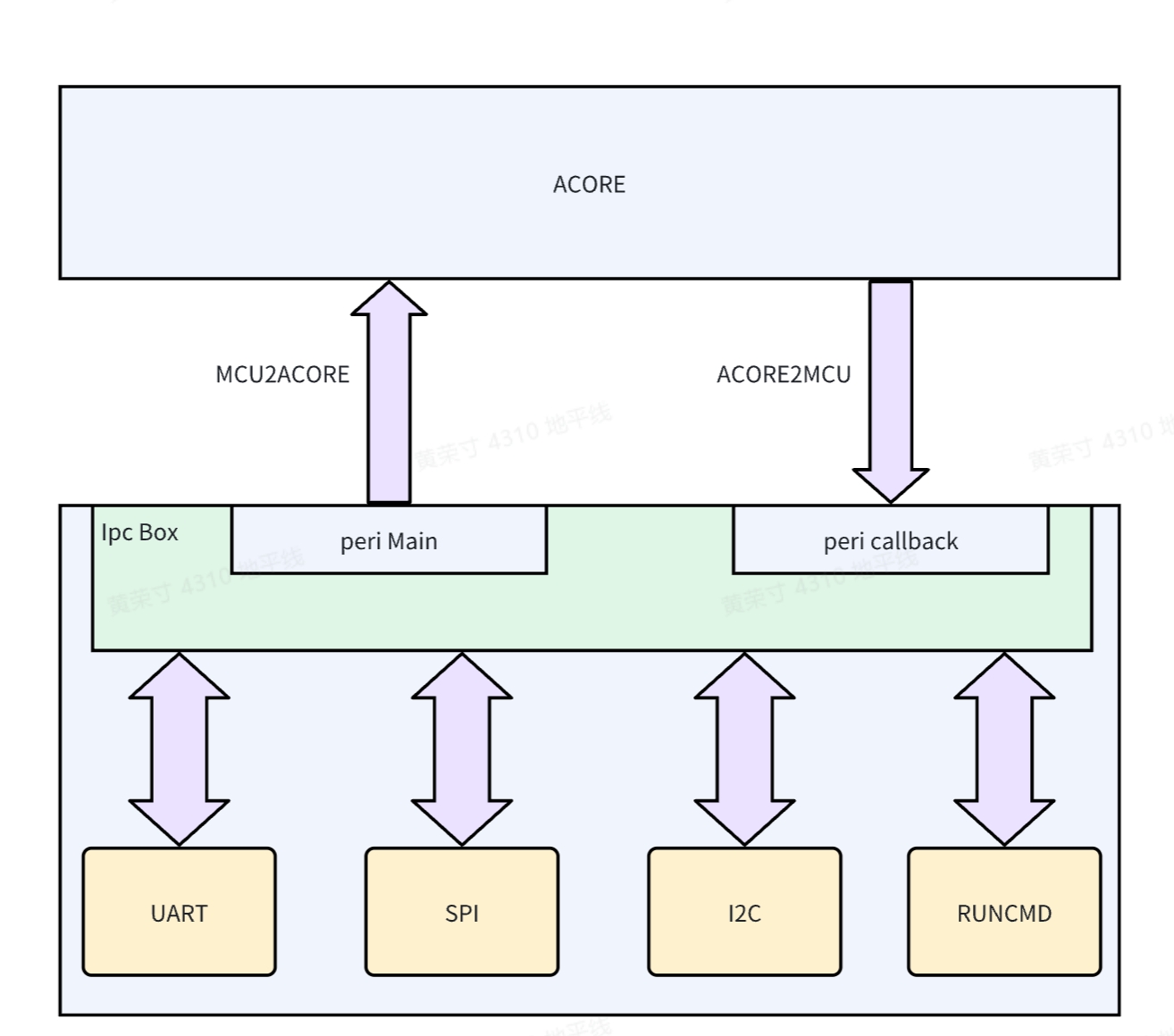
IpcBox 基于 MCU 侧的 IPC 通信框架增加的应用扩展,用于管理外设的透传功能,其实现框图如下:
各个外设通过统一的接口接入 IpcBox 中进行管理,简单来说就是外设数据经过 IPC Box 进行转发,并返回给 Acore 侧,同理 Acore 侧的数据通过 IpcBox 进行转发,并操作实际的外设,其数据流认为:Acore<->IPC<->MCU<->Peri
配套的 Acore 侧应用见IPC模块介绍 章节。
IpcBox 在版本 RDKS100的V4.0.4-Beta -> RDKS100的V4.0.5-Beta 升级过程中进行了一次重构,修改范围包括数据包结构,Ipc 通道,透传外设的默认配置,注意 MCU 侧和 Acore 侧的版本对应关系。
透传外设数据
实现情况:
| 项目 | 实现情况 | 备注 |
|---|---|---|
| RunCmd | 已实现 | 无 |
| SPI | 已实现 | 无 |
| I2C | 已实现 | 无 |
| Uart | 已实现 | 固定使用 Uart5 |
协议包解析
在一般情况下,一共占128字节,可以根据末尾数据域2扩展数据包长度,建议保持128字节,这样在为数据包申请64bytes 对齐的内存时,data[]数组仍为64bytes 对齐。
typedef struct {
    uint32 magic; // 魔数
    uint32 version; // 版本号
    uint32 checksum; // 校验和
    uint32 length; //数据包总长度
    char cmd[MAX_CMD_LENGTH]; // 数据域1
    uint8 reserve[48]; // 预留
    uint8 data[]; // 数据域2
} IpcBoxPacket_t;
使用方式
由于 IpcBox 会占用外设资源,所以在开机时,此功能是默认关闭的,如需要使用,请手动打开。 打开方式有以下两种:
- 通过修改 MCU SDK 中的数组配置,找到对应的外设,将
DISABLE改为ENABLE// Service/HouseKeeping/ipc_box/src/ipc_box.c
static Ipcbox_ComType IpcBox_InstanceMap[] = {
{ IPCBOX_COM_ID_RUNCMD, "runcmd", IpcConf_IpcInstance_IpcInstance_7,
IpcConf_IpcInstance_7_IpcChannel_0, ENABLE, IPCBOX_PERIID_INVALID,
IpcBox_RunCmdInit, IpcBox_RunCmdDeinit },
{ IPCBOX_COM_ID_UART, "uart", IpcConf_IpcInstance_IpcInstance_7,
IpcConf_IpcInstance_7_IpcChannel_1, DISABLE, UART5_CHANNEL,
IpcBox_UartInit, IpcBox_UartDeinit },
{ IPCBOX_COM_ID_SPI, "spi", IpcConf_IpcInstance_IpcInstance_7,
IpcConf_IpcInstance_7_IpcChannel_2, DISABLE, IPCBOX_PERIID_INVALID,
IpcBox_SpiInit, IpcBox_SpiDeinit },
{ IPCBOX_COM_ID_I2C, "i2c", IpcConf_IpcInstance_IpcInstance_7,
IpcConf_IpcInstance_7_IpcChannel_3, DISABLE, IPCBOX_PERIID_INVALID,
IpcBox_I2cInit, IpcBox_I2cDeinit },
}; - 这是临时打开的方式,可以通过 MCU1的命令行进行打开,如:
- 查看外设透传功能使能情况
D-Robotics:/$ ipcbox_set_mode debug
[066378.758965 0]Module: runcmd, Enable
[066378.759240 0]Module: uart, Enable
[066378.759663 0]Module: spi, Enable
[066378.760075 0]Module: i2c, Enable- 打开和关闭 IpcBox 透传 uart 外设功能
D-Robotics:/$ ipcbox_set_mode uart 1
[066386.990200 0]uart processing enabled
[066386.990487 0]IpcBox_FreeRtos_OsTask_IpcBox_Uart_ASW task is already initialized or running

D-Robotics:/$ ipcbox_set_mode uart 0
[066389.201404 0]uart processing disabled
[066389.267399 0]IpcBox_uart task resources released and terminating
[066389.701820 0]IpcBox_uart task exited properly- 打开和关闭 IpcBox 透传 I2C 外设功能
D-Robotics:/$ ipcbox_set_mode i2c 1
[066394.631826 0]i2c processing enabled
[066394.632101 0]IpcBox_FreeRtos_OsTask_IpcBox_I2c_ASW task is already initialized or running

D-Robotics:/$ ipcbox_set_mode i2c 0
[066397.082288 0]i2c processing disabled
[066397.085213 0]IpcBox_i2c task resources released and terminating
[066397.087215 0]IpcBox_i2c task exited properly- 打开和关闭 IpcBox 透传 SPI 外设功能
D-Robotics:/$ ipcbox_set_mode spi 1
[066403.227424 0]spi processing enabled
[066403.227699 0]IpcBox_Spi task is already initialized or running

D-Robotics:/$ ipcbox_set_mode spi 0
[066406.388582 0]spi processing disabled
[066406.389522 0]IpcBox_spi task resources released and terminating
[066406.393520 0]IpcBox_spi task exited properly
打印控制
IpcBox 模块的打印信息可以动态开关,由 ipcbox_loglevel 命令控制,
D-Robotics:/$ ipcbox_loglevel help
Usage: loglevel <level|subcommand>
  level: 0=NO_LOG, 1=ERROR, 2=WARN, 3=INFO, 4=DEBUG
  subcommands:
    show - show current log level
    help - show this message
输入ipcbox_loglevel 0后打印最少,输入ipcbox_loglevel 4后打印最多
D-Robotics:/$ ipcbox_loglevel 0
[066736.123326 0]This is an ERROR message

D-Robotics:/$ ipcbox_loglevel 4
[066738.473668 0]Log level changed to 4
[066738.473942 0]This is an ERROR message
[066738.474408 0]This is a WARN message
[066738.474853 0]This is an INFO message
[066738.475309 0]This is a DEBUG message
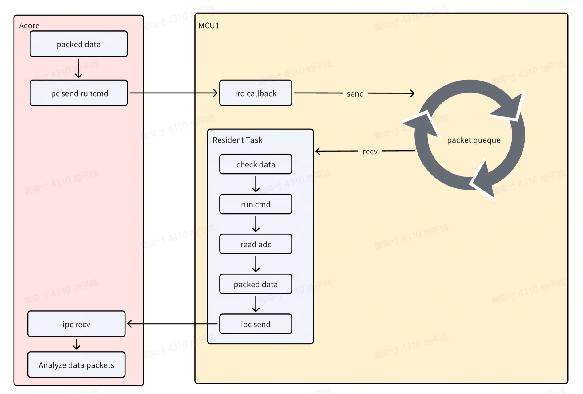
IpcBox RunCmd 的实现
根据 Acore 端传过来的命令,执行 MCU 侧的 CMD 应用,简称 RunCmd 应用。
各个外设经过 IPC Box 进行数据转发大同小异,实现原理主要分为以下两个过程:
Acore->Ipc->MCU过程- Acore 向 MCU 发送数据时触发 mcu 的中断,在中断的 callback 中将数据存储到队列中
MCU->Ipc->Acore过程- MCU 存在一个常驻线程,不断的在去读队列中的数据是否为空,若不为空,则校验并解析数据,识别出 cmd 命令并运行
- freertos 的 cmd 的应用类似于 uboot 的 cmd 的命令,通过此方式用户可以很方便的定制化自己的应用,在此场景中,运行的 cmd 将 adc 的值读出,再通过 ipc 返回给 Acore
IpcBox Uart 的实现
与 Runcmd 的实现类似,在此场景中,MCU 向 Acore 发送数据时触发 MCU 的中断,但并不会使用队列存储
实现原理主要分为以下两个过程:
Acore->Ipc->MCU过程- Acore 向 MCU 发送数据时触发 mcu 的中断,在中断解析数据,并通过 Uart 外设发出
MCU->Ipc->Acore过程- MCU 存在一个常驻线程,不断的调用 Uart 外设接收数据,当存在数据时,�将数据打包,转发到 Acore
IpcBox I2c 的实现
与 Runcmd 的实现类似,在此场景中,MCU 向 Acore 发送数据时触发 mcu 的中断,在中断的 callback 中将数据存储到队列中,然后通过 ipc 返回给 Acore 实现原理主要分为以下两个过程:
Acore->Ipc->MCU过程- Acore 向 MCU 发送数据时触发 mcu 的中断,在中断的 callback 中将数据存储到队列中
MCU->Ipc->Acore过程- MCU 存在一个常驻线程,不断的在去读队列中的数据是否为空,若不为空,则校验并解析数据
- 根据命令码实现 detect/get/set 操作。
- 由于 Slave 设备多样,例如地址宽度和操作步骤不同,所以 get/set 操作的实现不同,需要客户根据实际场景去实现
IpcBox_I2cGetValue和IpcBox_I2cSetValue,这两个 API 位于Service/HouseKeeping/ipc_box/src/ipc_i2c.c
IpcBox Spi 的实现
与 Runcmd 的实现类似,在此场景中,MCU 向 Acore 发送数据时触发 mcu 的中断,在中断的 callback 中将数据存储到队列中,然后通过 ipc 返回给 Acore 实现原理主要分为以下两个过程:
Acore->Ipc->MCU过程- Acore 向 MCU 发送数据时触发 mcu 的中断,在中断的 callback 中将数据存储到队列中
MCU->Ipc->Acore过程- MCU 存��在一个常驻线程,不断的在去读队列中的数据是否为空,若不为空,则校验并解析数据
- 根据命令码执行读写、只读、只写功能,由于 Spi 是全双工通信,所以只读其实是发送了等长度的无效数据,只写同理
应用程序接口
此部分为 MCU 侧的 IPC 接口。
void Ipc_MDMA_Init(Ipc_InstanceConfigType* pConfigPtr, uint32 InstanceId)
Description:Ipc MDMA Init.

Sync/Async: Synchronous
Parameters(in)
    pConfigPtr:the pointer to the device configuration parameter
    InstanceId:InstanceId id
Parameters(inout)
    None
Parameters(out)
    None
Return value:None
void Ipc_MDMA_DeInit(uint32 InstanceId)
Description:Subsystem driver deinitialization function.

Sync/Async: Synchronous
Parameters(in)
    InstanceId:InstanceId id
Parameters(inout)
    None
Parameters(out)
    None
Return value:None
void Ipc_GetVersionInfo(Std_VersionInfoType * versioninfo)
Description:get driver version.

Sync/Async: Synchronous
Parameters(in)
    None
Parameters(inout)
    versioninfo: the pointer to Version Info
Parameters(out)
    None
Return value:None
Std_ReturnType Ipc_MDMA_CheckRemoteCoreReady(uint32 InstanceId)
Description:check whether remote core is ready.

Sync/Async: Synchronous
Parameters(in)
    InstanceId:InstanceId id
Parameters(inout)
    None
Parameters(out)
    None
Return value:Std_ReturnType
    E_OK: remote core is ready
    IPC_E_PARAM_ERROR: param illegal
    IPC_E_DRIVER_NOT_INIT: Driver is not init
    IPC_E_INSTANCE_NOT_READY_ERROR : remote core is Not ready
    IPC_E_CHANNEL_NOT_OPEN: Instance is not open
void Std_ReturnType Ipc_MDMA_SendMsg(uint32 InstanceId, uint32 ChanId, uint32 Size, uint8* Buf, uint32 Timeout)
Description:send message.

Sync/Async: Synchronous
Parameters(in)
    InstanceId: Instance id
    ChanId: channel id
    Size: the size of buf to be sent
    Buf: the pointer to the memory that contains the buf to be sent
    Timeout: timeout(us)
Parameters(inout)
    None
Parameters(out)
    None
Return value:Std_ReturnType
    E_OK: success
    IPC_E_PARAM_ERROR: param is illegal
    IPC_E_DRIVER_NOT_INIT: Driver is not init
    IPC_E_CHANNEL_NOT_OPEN: Instance is not open
    IPC_E_TIMEOUT_ERROR: send timeout
    IPC_E_NO_MEMORY_ERROR: no memory to send buf
    PC_E_CHECKRESERROR: check resource error
dma 硬件要求传输地址16字节对齐,buffer 应该如下定义,首地址和 size16字节对齐: static uint8 attribute((aligned(16))) Ipc_Send_Buf[8192];
Std_ReturnType Ipc_MDMA_PollMsg(uint32 InstanceId)
Description:poll message If the Instance does not receive data using interrupts.

Sync/Async: Synchronous
Parameters(in)
    InstanceId: Instance id
Parameters(inout)
    None
Parameters(out)
    None
Return value:Std_ReturnType
    E_OK: success
    IPC_E_PARAM_ERROR: param is illegal
    IPC_E_DRIVER_NOT_INIT: Driver is not init
    IPC_E_CHANNEL_NOT_OPEN: Instance is not open
    IPC_E_NO_DATA_TO_RECEIVE_ER ROR: No data to be recvived
Std_ReturnType Ipc_MDMA_OpenInstance(uint32 InstanceId)
Description:Open a Instance pointed to by ID.

Sync/Async: Synchronous
Parameters(in)
    InstanceId: Instance id
Parameters(inout)
    None
Parameters(out)
    None
Return value:Std_ReturnType
    E_OK: success
    IPC_E_DRIVER_NOT_INIT: Driver is not init
    IPC_E_CHANNEL_NOT_CLOSE: Instance has been opened
    IPC_E_PARAM_ERROR param is illegal
Std_ReturnType Ipc_MDMA_CloseInstance(uint32 InstanceId)
Description:close a Instance pointed to by ID.

Sync/Async: Synchronous
Parameters(in)
    InstanceId: Instance id
Parameters(inout)
    None
Parameters(out)
    None
Return value:Std_ReturnType
    E_OK: success
    IPC_E_DRIVER_NOT_INIT: Driver is not init
    IPC_E_CHANNEL_NOT_CLOSE: Instance has been opened
    IPC_E_PARAM_ERROR param is illegal
Std_ReturnType Ipc_MDMA_TryGetHwResource(uint32 InstanceId, uint32 ChanId, uint32 BufSize)
Description:try get Hardware resource.

Sync/Async: Synchronous
Parameters(in)
    InstanceId ChanId BufSize: Instance id Chanel Id buf size
Parameters(inout)
    None
Parameters(out)
    None
Return value:Std_ReturnType
    E_OK: success
    IPC_E_DRIVER_NOT_INIT: Driver is not init
    IPC_E_DEVICE_BUSY: Instance is busy.
    IPC_E_MDMA_BUSY: Send MDMA is busy.
    IPC_E_NO_BUF_ERROR: no buffer
    IPC_E_CHANNEL_NOT_OPEN: Instance has been closed