ethernet
Preface
The S100 chip provides multiple standard Gigabit/10-Gigabit Ethernet controllers, supporting traditional Ethernet packet收发, PTP/TSN time-sensitive networking, and EtherCAT master features.
The S600 chip provides multiple standard Gigabit/10-Gigabit Ethernet controllers, supporting traditional Ethernet packet收发, PTP/TSN time-sensitive networking, and EtherCAT master features.
The controllers have built-in hardware multi-queue, MTL layer 2 transport layer, DMA engine, etc., to achieve packet收发 in the various scenarios mentioned above.
This document mainly includes a network card usage guide, development board Bringup, and key feature descriptions.
Terminology
| Abbreviation | Full Name | Explanation |
|---|---|---|
| PTP | Precision Time Protocol | Precision Time Protocol |
| PHC | PTP Hardware Clock | PTP Hardware Clock |
| TSN | Time-Sensitive Networking | Time-Sensitive Networking |
| CBS | Credit-Based Shaper | Credit-Based Shaper |
| EST | Enhancements to Scheduled Traffic | Enhancements to Scheduled Traffic |
| FPE | Frame Preemption | Frame Preemption |
| tc | traffic control | Traffic Control |
Network Card Feature Introduction
| Feature | Description | S100 |
|---|---|---|
| Configuration | Number of Ethernet ports | Dual-port |
| Interface | MAC-PHY interface | Supports SGMII |
| PPS | Pulse Per Second, pps out/in | ✅ |
| TSO | TCP Segmentation Offload | ✅ |
| Multi-queue | NIC multi-queue feature | ✅ |
| AVB/TSN | Time-Sensitive Networking | ✅ |
| C22/C45 | MDIO PHY data protocol | ✅ |
| Feature | Description | S600 |
|---|---|---|
| Configuration | Number of Ethernet ports | 3x gmac + 3x xgmac First 2 gmacs share PHY with PCIe |
| Interface | MAC-PHY interface | Supports SGMII/USXGMII |
| PPS | Pulse Per Second, pps out/in | ✅ |
| TSO | TCP Segmentation Offload | ✅ |
| Multi-queue | NIC multi-queue feature | ✅ |
| AVB/TSN | Time-Sensitive Networking | ✅ |
| C22/C45 | MDIO PHY data protocol | ✅ |
Network Configuration
U-Boot
- Configure IP
      setenv ipaddr x.x.x.x
      setenv gatewayip x.x.x.x
      setenv netmask x.x.x.x
- Configure VLAN
setenv vlan xx
- Configure MAC Address
      setenv ethaddr xx:xx:xx:xx:xx:xx          //set eth mac address
      env del -f ethaddr                        //delete mac address
- Switch current eth
      setenv ethact eth0
      setenv ethact eth1
      # Switching is possible if U-Boot supports dual NICs. Switching is invalid for single NIC.
Linux/Ubuntu
- It is recommended to use Network Management, i.e., the Ubuntu desktop, for network card configuration.
- Manual configuration using commands like ip, ethtool below is the secondary option. Determine whether it takes effect based on your Ubuntu version and online resources.
- Configure IP
      ip addr add 192.168.1.10/24 dev eth0.10 //recommended
      or
      ifconfig eth0.10 192.168.1.10 netmask 255.255.255.0
- Configure VLAN
      ip link add link eth0 name eth0.10 type vlan id 10                                //add vlan id 10
      ip link set eth0.10 type vlan egress 0:5 1:5 2:5 3:5 4:5 5:5 6:5 7:5          //configure vlan priority 5
Software Introduction
Code Location
- U-Boot ETH Code Location
    drivers/net/hobot_super_gmac.c
    drivers/net/hobot_super_xpcs.c
    drivers/net/hobot_super_xgmac.c
    drivers/net/hobot_s600_xpcs.c
- Kernel ETH Code Location
   hobot-drivers/ethernet/hobot/hobot_eth_super_main.c
   hobot-drivers/ethernet/hobot/hobot_eth_super_mdio.c
   hobot-drivers/ethernet/hobot/hobot_eth_super_ptp.c
   hobot-drivers/ethernet/hobot/hobot_eth_super_tc.c
   hobot-drivers/ethernet/hobot/core/...
   hobot-drivers/ethernet/hobot/dma/...
Network Driver Development
U-Boot ETH Development
Hardware Connection
- Refer to S100 Design Schematic
- Refer to S600 Design Schematic
Device Tree Configuration
    // Configure hsis mode and reference clock selection, such as combo PHY multiplexing, reference clock source, etc.
    hsis0: hsis0 {
        status = "okay";
        compatible = "hobot,super-hsis";
        hsi-mode = <4>; /* 4:pcie x2 + gmac0/1; 8:pcie0 x1 + pcie1 x1 + GMAC0/1; */
        refclk-mode = <0>; /* 0:internal ref clock; 1:external ref clock; */
        #address-cells = <2>;
        #size-cells = <2>;
        ranges;
        /*hsis reg, XPCS0, XPCS1, ETH phy, PCIE phy*/
        reg = <0x0 0x33000000 0x0 0x10000>,
            <0x0 0x33200000 0x0 0x80000>,
            <0x0 0x33280000 0x0 0x80000>,
            <0x0 0x330e0000 0x0 0x10000>,
            <0x0 0x330d0000 0x0 0x10000>;
    };
    // Configure hsis mode and reference clock selection, such as combo PHY multiplexing, reference clock source, and PHY eye diagram signal parameters.
    hsis0: hsis0 {
        status = "okay";
        compatible = "hobot,super-hsis";
        hsi-mode = <4>;
        refclk-mode = <0>;/* 0:internal; 1:external; */
        xpcs-speed = <0 0 0 5000 10000 10000>; /*gmac0, gmac1, gmac2, xgmac0, xgmac1, xgmac2*/
        hobot-txeq = <0 0 0 1 2 4>; /* gmac0/1/2 xgmac0/1/2 tx equalization control*/
        hobot-vboost = <5 5 5 5 5 5>; /*gmac0/1/2 xgmac0/1/2*/
        #address-cells = <2>;
        #size-cells = <2>;
        ranges;
        /*hsis reg, XPCS0, XPCS1, ETH phy, PCIE phy, XPCS2, XPCS3,XPCS4, XPCS5*/
        reg = <0x0 0x33000000 0x0 0x10000>,
            <0x0 0x33200000 0x0 0x80000>,
            <0x0 0x33280000 0x0 0x80000>,
            <0x0 0x330e0000 0x0 0x10000>,
            <0x0 0x330d0000 0x0 0x10000>,
            <0x0 0x33300000 0x0 0x80000>,
            <0x0 0x33380000 0x0 0x80000>,
            <0x0 0x33400000 0x0 0x80000>,
            <0x0 0x33480000 0x0 0x80000>;
    };
- xpcs-speed: Set xpcs according to different speeds.
- hobot-txeq: Set eye diagram parameters for different gears, range [0, 10], default is gear 4, no adjustment needed for sgmii.
- hobot-vboost: Eye diagram amplitude coefficient, 0 disables.
mdio phy Configuration
- Refer to schematics and hardware documentation for PHY connection details.
- Software mainly needs to focus on the reset pin and phy addr address.
// drobot-s100-soc.dtsi, default eth configuration for the chip; can be overridden by specific board's dts
eth0: eth0 {
status = "disabled";
compatible = "hobot,super-gmac";
/*MAC, XPCS, ETH PHY, PCIE PHY, hsis reg*/
reg = <0x0 0x330f0000 0x0 0x10000>,
<0x0 0x33200000 0x0 0x80000>;
phy-handle = <&phy1>;
phy-mode = "sgmii";
managed = "in-band-status";
pinctrl-names = "default";
pinctrl-0 = <&peri_emac>;
#address-cells = <1>;
#size-cells = <0>;
};
// drobot-s100-rdk.dts, configure properties based on actual board conditions. Mainly phy node, reset pin, phy addr, etc.
// Also mdio pinmux, function configuration, etc.
ð0 {
status = "okay";
hobot,managed = "sgmii-autoneg";
phy-handle = <&phy0>;
phy-reset-gpios = <&hsi_port0 10 0>;
#address-cells = <1>;
#size-cells = <0>;
phy0: phy@0 {
compatible = "ethernet-phy-ieee802.3-c22";
reg = <0xe>;
};
};
// hobot-s600-soc.dtsi, default eth configuration for the chip. Can be overridden by specific board's dts.
eth2: gmac2 {
status = "disabled";
compatible = "hobot,super-gmac";
/*MAC, XPCS*/
reg = <0x0 0x33110000 0x0 0x10000>,
<0x0 0x33380000 0x0 0x80000>;
phy-mode = "sgmii";
#address-cells = <1>;
#size-cells = <0>;
fixed-link {
speed = <1000>;
full-duplex;
};
};
// drobot-s600-rdk.dts, configure properties based on actual board conditions. Mainly phy node, reset pin, phy addr, etc.
// Also mdio pinmux, function configuration, etc.
ð2 {
status = "okay";
hobot,managed = "sgmii-autoneg";
phy-handle = <&phy2>;
pinctrl-names = "default";
pinctrl-0 = <&hsi_emac_mdc_hsi2_emac_mdc_hsi2 &hsi_emac_mdio_hsi2_emac_mdio_hsi2>;
phy2: phy@2 {
#address-cells = <1>;
#size-cells = <0>;
reset-gpios = <&gpio_exp_24 8 GPIO_ACTIVE_LOW>;
reset-delay-us = <10000>;
reset-post-delay-us = <150000>;
compatible = "ethernet-phy-ieee802.3-c22";
reg = <0x2>;
};
};
MAC2MAC
- In MAC TO MAC direct connection scenarios, configure as fixed-link.
- For example:
// Default eth0 node configuration can refer to drobot-s100-soc.dts
// Actual board-level configuration can be described in the corresponding dts, e.g., refer to drobot-s100-rdk.dts.
// For MAC2MAC scenarios, the main thing is to configure fixed-link mode, i.e., fixing speed, duplex mode, etc.
ð0 {
status = "okay";
fixed-link {
speed = <1000>;
full-duplex;
};
};
// Similar for S600 development board, override to fixed-link mode in the board-level dts.
ð3 {
status = "okay";
fixed-link {
speed = <10000>;
full-duplex;
};
};
U-Boot Commands Introduction
- mii: PHY read/write commands (C22 protocol) The network interface is initialized after executing network commands (e.g., ping), otherwise mdio commands may execute abnormally.
      mii info   <addr>                    //display MII phy info
      mii read   <addr> <reg>              //read  MII phy <addr> register <reg>
- mdio: PHY read/write commands (C45)
      mdio list                           //List MDIO buses
      mdio read <phydev> [<devad>.]<reg>  //read phy register at <devad>.<reg>
- md: View statistics
Use md command to read/write registers to view packet statistics for debugging.
md[.b, .w, .l, .q] address
Linux ETH Development
- Driver code is in the hobot-drivers/ethernet directory, refer to the description in Software Introduction.
- Most of the controller driver part does not require modification; the main task is to configure the relevant device tree based on the development board hardware.
hsis Mode Configuration
- Since the PHY parts of S100 Ethernet and PCIe have multiplexing relationships, special attention must be paid to the configuration of the hsis module.
- This includes lane usage configuration and reference clock configuration. Particularly note that U-Boot also configures it once during startup,
- so ensure that the U-Boot hsis configuration is consistent with the Kernel's. Otherwise, actual lane configuration may be incorrect.
- Since the PHY parts of S600 Ethernet and PCIe have multiplexing relationships, special attention must be paid to the configuration of the hsis module.
- This includes lane usage configuration and reference clock configuration. Particularly note that U-Boot also configures it once during startup,
- so ensure that the U-Boot hsis configuration is consistent with the Kernel's. Otherwise, actual lane configuration may be incorrect.
    &hsis0 {
            hsi-mode = <0x4>;  /* 0x1: pcie x4, 0x4: pcie x2 + gmac0 + gmac1, 0x8: pcie0 x1 + pcie1 x1 + gmac0 + gmac1 >
            refclk-mode = <0>; /* 0:internal; 1:external; */
    };
    &hsis0 {
            hsi-mode = <2>;  /* 0x1: pcie x4, 0x2: pcie x2x2, 0x4: pciex2 + ethx2 */
            refclk-mode = <0>; /* 0:internal; 1:external; */

            xpcs-speed = <0 0 0 1000 10000 10000>;  /*gmac0, gmac1, gmac2, xgmac0, xgmac1, xgmac2*/
            hobot-txeq = <0 0 0 1 2 4>; /* gmac0/1/2 xgmac0/1/2 tx equalization control*/
            hobot-vboost = <5 5 5 5 5 5>; /*gmac0/1/2 xgmac0/1/2*/
    };
Network Card and PHY Configuration
// Default network card node can refer to drobot-s100-soc.dtsi
// Board-level related configuration depends on actual hardware connections. For traditional sgmii phy mode, refer to nodes in rdk-v0p5.dtsi.
ðernet0 {
status = "okay";
phy-handle = <&phy0>;
hobot,managed = "sgmii-autoneg";
pinctrl-names = "default";
pinctrl-0 = <&peri_emac>;
mdio {
#address-cells = <0x1>;
#size-cells = <0x0>;
phy0: phy@0 {
compatible = "ethernet-phy-ieee802.3-c22";
reg = <0x2>;
};
};
};
// Default network card node can refer to drobot-s600-soc.dtsi
// Board-level related configuration depends on actual hardware connections. For traditional sgmii phy mode, refer to nodes in rdk-s600-mcb.dtsi.
/* gmac2 */
ðernet2 {
status = "okay";
phy-handle = <&phy2>;
hobot,managed = "sgmii-autoneg";
pinctrl-names = "default";
phy-mode = "sgmii";
pinctrl-0 = <&hsi_emac_mdc_hsi2_emac_mdc_hsi2 &hsi_emac_mdio_hsi2_emac_mdio_hsi2>;
mdio {
#address-cells = <0x1>;
#size-cells = <0x0>;
reset-gpios = <&gpio_exp_24 8 GPIO_ACTIVE_LOW>;
reset-delay-us = <10000>;
reset-post-delay-us = <150000>;
phy2: phy@2 {
compatible = "ethernet-phy-ieee802.3-c22";
reg = <0x2>;
};
};
};
Common MAC and PHY Configurations
- Refer to the device tree content above and more complete information in dts files.
- Describe common phy configuration parameters:
- reset-delay-us: Indicates reset time.
- reset-post-delay-us: Indicates delay time after de-asserting reset (time from de-assert to PHY initialization completion).
- ethernet-phy-ieee802.3-c22: mdio compatible name, indicating the PHY MDIO uses the C22 protocol.
Common examples like RTL Gigabit PHYs support this protocol. - ethernet-phy-ieee802.3-c45: mdio compatible name, indicating the PHY MDIO uses the C45 protocol.
Refer to manual for 10-Gigabit PHYs and some high-end PHYs that use the C45 protocol.
- Common MAC-related configurations:
- sgmii-autoneg: Configure SGMII auto-negotiation.
- phy-mode: Connection method with the PHY, e.g., sgmii, usxgmii, etc.
- xpcs-speed: XPCS operating speed, e.g., configure as 1000 to force XPCS to 1G sgmii mode.
- hobot,xgmac_gmii: XGMAC operates in GMII mode.
- For more advanced feature configurations, refer to subsequent sections.
MAC2MAC
- Similar to U-Boot, for MAC2MAC scenarios, the main thing is to configure fixed-link mode.
- S100
- S600
// Default eth0 node configuration can refer to drobot-s100-soc.dts
// Actual board-level configuration can be described in the corresponding dts, e.g., refer to drobot-s100-rdk.dts.
// For MAC2MAC scenarios, the main thing is to configure fixed-link mode, i.e., fixing speed, duplex mode, etc.
ðernet0 {
status = "okay";
fixed-link {
speed = <1000>;
full-duplex;
};
};
// Similar for S600 development board, override to fixed-link mode in the board-level dts.
ðernet2 {
status = "okay";
fixed-link {
speed = <10000>;
full-duplex;
};
};
- Description of common fixed-link node attributes:
- speed (integer, required): Indicates link speed, can be set to 10, 100, 1000.
- full-duplex (boolean, optional): Indicates duplex mode, default is half-duplex.
- pause (boolean, optional): Indicates whether to enable pause, default is disabled.
- asym-pause (boolean, optional): Indicates whether to enable asym-pause, default is disabled.
- link-gpio (gpio-list, optional): Indicates whether to read GPIO to determine if the link is up.
TSO
- TCP Segmentation Offload, modern NIC hardware supports TCP segmentation offload to reduce CPU load for TCP segmentation tasks.
- When TSO is enabled, the kernel's GSO (Generic Segmentation Offload) is automatically enabled.
- TSO functionality can be controlled via the hobot,tso flag.
hobot,tso = <1>; // Enable NIC TSO functionality
Configure XGMAC to 1G Mode
- This feature is only needed for S600 10-Gigabit NICs. (S100 defaults to 1G Gigabit mode)
- Mainly configured via device tree hsis and the corresponding NIC node, for example:
    hsis0: hsis0 {
        status = "okay";
        compatible = "hobot,super-hsis";
        xpcs-speed = <0 0 0 1000 10000 10000>; /*gmac0, gmac1, gmac2, xgmac0, xgmac1, xgmac2*/
    };
    ethernet3: xgmac0@0x33130000 {
        compatible = "hobot,hobot_xgmac";
        hobot,xgmac_gmii;
    };
- xpcs-speed: Configure XPCS to operate in 1G SGMII mode with 1000.
- hobot,xgmac_gmii: Force XGMAC to operate in GMII mode.
Interrupt Coalescing
    ethernet3: xgmac0@0x33130000 {
        compatible = "hobot,hobot_xgmac";
        hobot,disable_coal;
    };
- hobot,disable_coal; # Interrupt coalescing is enabled by default on the NIC; this flag can be used to disable it.
RSS
- Receive Side Scaling, a receive-side load balancing technology supported by multi-queue NIC hardware.
- Typically for 10-Gigabit NICs, e.g., S600 requires this technology.
    ethernet3: xgmac0@0x33130000 {
        compatible = "hobot,hobot_xgmac";
        hobot,multi_irq;
        hobot,rss_en;
    };
- RSS Receive Side Scaling technology, simply put, the NIC hardware calculates the hash value of the packet's 5-tuple (IP, port, protocol), and then distributes NIC interrupts to different cores based on relevant strategies to achieve receive-side CPU load balancing.
- Therefore, this technology relies on the NIC hardware's hash algorithm, RSS feature support, and the NIC's multi-interrupt mechanism.
- hobot,multi_irq; # NIC multi-interrupt support, registering different ISRs for multiple interrupts.
- hobot,rss_en; # Enable NIC receive-side scaling functionality.
HSIS, XPCS
    hsis0: hsis0 {
        status = "okay";
        compatible = "hobot,super-hsis";
        hsi-mode = <4>;
        refclk-mode = <0>;/* 0:internal; 1:external; */
        xpcs-speed = <0 0 0 5000 10000 10000>; /*gmac0, gmac1, gmac2, xgmac0, xgmac1, xgmac2*/
        hobot-txeq = <0 0 0 1 2 4>; /* gmac0/1/2 xgmac0/1/2 tx equalization control*/
        hobot-vboost = <5 5 5 5 5 5>; /*gmac0/1/2 xgmac0/1/2*/
    };
- The hsis and xpcs configurations during boot use the hsis configuration from U-Boot.
- The hsis configuration in Linux is only used to restore hsis mode and xpcs mode during suspend/resume.
- Therefore, when modifying hsis configuration, ensure it is synchronously modified with the U-Boot hsis node.
Queues
- Modern network cards are multi-queue NICs.
- Queue scheduling policies, priority configuration, etc., can be configured via the device tree.
    ethernet4: xgmac0@0x33140000 {
        compatible = "hobot,hobot_xgmac";
        hobot,mtl-rx-config {
            hobot,rx-queues-to-use = <8>;
            hobot,rx-sched-sp;
            queue0 {
                hobot,dcb-algorithm;
                hobot,priority = <0x1>;
            };
            queue1 {
                hobot,avb-algorithm;
                hobot,route-ptp;
            };
            ...
        };
        hobot,mtl-tx-config {
            hobot,tx-queues-to-use = <8>;
            hobot,tx-sched-wrr;
            queue0 {
                hobot,dcb-algorithm;
            };
            queue1 {
                hobot,avb-algorithm;
                hobot,priority = <0x2>;
            };
            ...
        };
    };
- hobot,mtl-tx-config configuration:
| Attribute | Description |
|---|---|
| hobot,tx-sched-wrr | Round-robin scheduling for multi-queue. RR scheduling can be chosen when no TSN or service priority requirements exist. |
| hobot,tx-sched-sp | Strict priority scheduling |
| hobot,avb-algorithm | Send queue AVB mechanism can be used for TSN |
| hobot,dcb-algorithm | Queue 0 and RR scheduling must be configured in DCB mode |
- hobot,mtl-rx-config configuration:
| Attribute | Description |
|---|---|
| hobot,rx-sched-sp | Receive strict priority scheduling; no RR scheduling for receive queues. |
| hobot,avb-algorithm | Receive queue AVB mechanism can be used to receive gPTP packets. |
| hobot,dcb-algorithm | DCB mechanism used to select receive queue based on VLAN priority, thus allowing different NAPI threads to handle tasks of different priorities. |
- Configure queue scheduling mechanisms and queue modes according to service requirements.
- When configured for multi-queue, queues share hardware buffers equally. If multi-queue is not required, you can keep only one queue to monopolize all hardware buffers.
Common Network Card Commands
ethtool
- ethtool: View statistics, configure PHY, etc., supports the following commands:
    # View statistics
    ethtool -S eth0

    # Display timestamping capabilities
    ethtool -T eth0

    # Perform Loopback test
    ethtool -t eth0 offline

    # Control TSO feature on/off
    ethtool -K eth0 tso on/off

    # Control checksum feature on/off
    ethtool -K eth0 rx-checksum on/off

    # Switch network speed
    ethtool -s eth0 speed 100 duplex full autoneg on

    # Enable frame preemption
    ethtool hobot_gmac --set-fp eth0 fp on
vconfig
- Configure VLANs.
- Can be replaced by ip command.
vconfig add eth0 3
iperf3
- Bandwidth, packet loss testing, etc.
- Test commands:
   server: iperf3 -s
   client tcp: iperf3 -c serverip -t 60
   client udp: iperf3 -c serverip -u -b 1G -l 8K -t 60
tcpdump
- Packet capture tool.
- Test commands:
    tcpdump -i eth1 -e              # Filter packets and output to terminal
    tcpdump -i eth1 -w eth1.pcap    # Filter packets and save to file, can be analyzed with wireshark
phytool
- This tool can be used to read and set c22/c45 PHY registers.
- Example:
    # Help information
    ADDR := C22 | C45
    C22 := <0-0x1f>
    C45 := <0-0x1f>:<0-0x1f>

    phytool read IFACE/ADDR/REG
    phytool write IFACE/ADDR/REG <0-0xffff>

    # Example
    root@hobot:~# phytool read eth0/0x7:1/2
    0x002b

    root@hobot:~# phytool read eth1/0xE/2
    0x0141
Network Card Time Synchronization
- Includes PTP, PPS, PHC, and other technologies.
PPS
- Pulse Per Second. A time synchronization mechanism at the NIC hardware level. Typically used with PTP (IEEE 1588)/gPTP. To achieve time synchronization between automotive and robotic systems.
- Divided into pps in and pps out, i.e., can act as a slave device receiving high-precision pulse-per-second signals from external sources, or as a master device outputting pulse-per-second signals.
pps in
- pps in is used as the trigger source for the snapshot of the Ethernet PHC time.
pps out
- eth pps only supports a single pps out.
- Can be configured and tested with the following commands:
ethtool hobot_gmac --set-flex-pps eth0 index 0 fpps on interval 1000000000
PHC snapshot
- Ethernet PTP Hardware Clock, hardware timestamp for NIC time synchronization.
- Obtain PHC snapshot time to calculate time differences.
- Example usage:
    // Open PHC device
    phcfd = open(“/dev/ptp0”, O_RDWR);

    // Set PHC snapshot source via ioctl
    struct ptp_extts_request extts_request;
    extts_request.index = phc_snapshot_source;
    extts_request.flags = PTP_ENABLE_FEATURE;
    ioctl(phcfd, PTP_EXTTS_REQUEST, &extts_request);

    // Get PHC time via read interface
    struct ptp_extts_event event;
    read(phcfd, &event, sizeof(event));
    phctime->tv_sec = event.t.sec;
    phctime->tv_nsec = event.t.nsec;

    // Set PHC time, after execution, PHC time will be increased by offset
    clockadj_step(FD_TO_CLOCKID(phcfd), offset);

    // Close PHC device
    close(phcfd);
Time Synchronization gptp
Application Layer Interface
- POSIX network and PTP hardware clock API mapping table
| Function Category | Core POSIX API Code |
|---|---|
| L2 packet收发 | socket(PF_PACKET, SOCK_RAW, htons(ETH_P_ALL));bind(fd, (struct sockaddr *) &addr, sizeof(addr));setsockopt(fd, SOL_SOCKET, SO_BINDTODEVICE, name, strlen(name)); /* Bind to specific NIC */setsockopt(fd, SOL_SOCKET, SO_ATTACH_FILTER, &prg, sizeof(prg)); /* Attach packet filter */ioctl(sock, SIOCGIFHWADDR, &ifr); /* Get NIC MAC address */ |
| Packet Hardware Timestamping | ioctl(fd, SIOCSHWTSTAMP, &ifreq); /* Enable hardware timestamping */setsockopt(fd, SOL_SOCKET, SO_TIMESTAMPING, &flags, sizeof(flags)); /* Enable timestamping delivery */recvmsg(fd, &msg, MSG_ERRQUEUE); /* Get transmit packet hardware timestamp */recvmsg(fd, &msg, 0); /* Get receive packet hardware timestamp */ |
| Get NIC PHC Index | socket(AF_INET, SOCK_DGRAM, 0);ioctl(fd, SIOCETHTOOL, &ifr); |
| PHC Time Read/Write | open("/dev/ptp0", O_RDWR);FD_TO_CLOCKID(fd);clock_gettime(clkid, &ts);clock_settime(clkid, &ts); |
| PHC Frequency Adjustment | clock_adjtime(clkid, &tx); /* Adjust frequency, time offset */ |
Time Synchronization Steps
- Master
ptp4l -P -H -2 -i eth0 -p /dev/ptp0 -m
- Slave
ptp4l -P -H -2 -i eth0 -p /dev/ptp0 -m -s -l 7
- Other
- For more detailed configuration, refer to automotive-master.cfg, automotive-slave.cfg in the linuxptp source code of third-party tools, e.g., to reduce PTP synchronization completion time.
TSN
TSN Introduction
- Time-Sensitive Networking.
- TSN consists of a series of technical standards, mainly divided into three parts related to common standards: clock synchronization, data scheduling (i.e., shapers), and system configuration.
TSN-VLAN
- TSN refers only to the Layer 2 Data Link Layer standard of the ISO/OSI reference model in IEEE 802.1Q.
- The VLAN of the 802.1Q standard inserts 4 bytes into the standard Ethernet frame to define its characteristics. The tag bits of TSN are shown in the figure below:
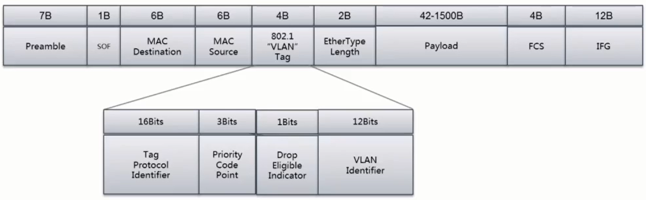
- For TSN networks, services with different priorities or Classes of Service (CoS) correspond to the PCP code in the figure above. The Priority Code Point (PCP) consists of 3 bits; the 3-bit PCP code defines 8 priorities from 0 (lowest) to 7 (highest), with transmission types corresponding to Best Effort, Excellent Effort, Critical Applications, Video (<100ms delay and jitter), Audio (<10ms delay and jitter), Internetwork Control, and Network Control, respectively.
Multi-queue
- VLAN priorities and multiple protocols require multiple queues to handle; multi-queue is the foundation for implementing TSN.
- The mapping of packets to queues is implemented by the ndo_select_queue method in the NIC driver.
Data Scheduling (Shaper)
Credit-Based Shaper (CBS) (IEEE 802.1-Qav)
- Each queue is set with a certain credit value, corresponding to bandwidth based on the credit value. CBS divides queues into Class A (Tight delay bound) and Class B (Loose delay bound).
Enhancements to Scheduled Traffic (EST) (IEEE 802.1Qbv-2015)
- EST is defined by IEEE 802.1Qbv, also known as TAS (Time Awareness Shaper). It is a mechanism that dynamically provides on/off control for egress queues based on a pre-set periodic gate control list. Qbv defines a time window. This window is pre-determined in the mechanism. The gate control list is scanned periodically and opens transmission ports for different queues in a pre-defined order.
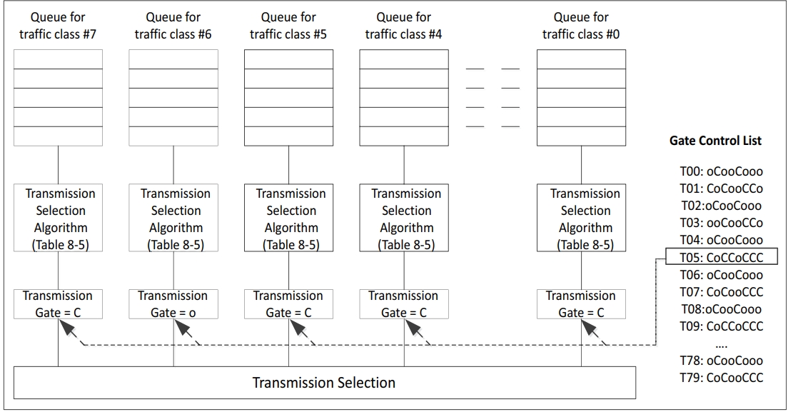
- Block diagram of the IEEE 802.1Qbv specification, illustrating how the gate control list manages gate close (C-close) and open (O-open) events based on the schedule provided for each event.
- The GCL has the following two parts:
- Time interval: Defines the time, in nanoseconds, for which the gate control item is valid before reading the next gate control item from the list.
- Gate control: Defines the state of the gate for each TC, either logic 1 indicating open (O-open) or logic 0 indicating close (C-close).
Frame Preemption (FPE) (IEEE 802.1Qbu-2016)
- To address the waste of protection bandwidth and priority inversion issues of EST, the preemption standard was introduced. Therefore, TSN's 802.1Qbu and the IEEE 802.3 working group jointly developed IEEE 802.3br, the preemptable MAC mechanism, consisting of pMAC (Preemptable MAC) and eMAC (express MAC). pMAC can be preempted by eMAC. Through preemption, the protection bandwidth can be reduced to the shortest low-priority frame fragment.
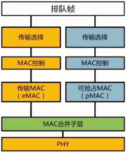
- Since preemption changes the frame format, the peer switch also needs to support FPE when connecting.
Configuration Verification
tc
- For various TSN features, the Linux-native tc command (Traffic Control) is typically used for configuration and verification.
- Supports the following methods:
SHAPING, SCHEDULING, POLICING, DROPPING
CBS
- Command format:
tc qdisc ... dev dev parent classid [ handle major: ] cbs idleslope <idleslope> sendslope <sendslope> hicredit <hicredit> locredit <locredit> [ offload 0|1 ]
- Verification:
    ## Configure CBS qdisc, set queue 1 bandwidth to 40Mbps, test bandwidth
    root@hobot:~# tc qdisc add dev eth0 parent root handle 6666 mqprio num_tc 2 map 0 1 0 0 0 0 1 0 0 0 0 0 0 0 0 0 queues 1@0 1@1 hw 0

    root@hobot:~# tc qdisc replace dev eth0 parent 6666:2 cbs idleslope 40000 sendslope -960000 hicredit 60 locredit -1440 offload 1

    root@hobot:~# tperf eth0 10000 1
    sending 10000 packets: prio=0x1 (class B)
    10000 packets: 9.708405 MB in 2044712 us
    39.829567 Mbps
EST
- Command format:
    tc qdisc ... dev dev parent classid [ handle major: ] taprio num_tc tsc  map P0 P1 P2 ...  queues count1@offset1 count2@offset2 ...  base-time base-time clockid clockid
    sched-entry <command 1> <gate mask 1> <interval 1>
    sched-entry <command 2> <gate mask 2> <interval 2>
    sched-entry <command 3> <gate mask 3> <interval 3>
    sched-entry <command N> <gate mask N> <interval N>
    ...
    flags  number
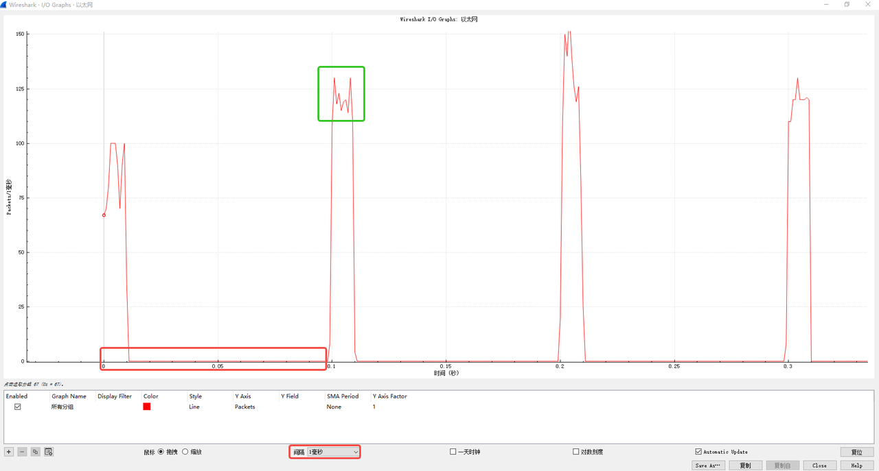
- Verification:
    ## Queue 3 sends every 100ms, once for 10ms
    root@hobot:~# ptp4l -P -H -2 -i eth0 -p /dev/ptp0 -m &

    root@hobot:~# tc qdisc replace dev eth0 parent root handle 100 taprio num_tc 4 map 0 1 2 3 queues 1@0 1@1 1@2 1@3 base-time 1000 sched-entry S 8 10000000 sched-entry S 0 10000000 sched-entry S 0 10000000 sched-entry S 0  10000000 sched-entry S 0  10000000 sched-entry S 0  10000000 sched-entry S 0  10000000 sched-entry S 0  10000000 sched-entry S 0  10000000 sched-entry S 0  10000000 flags 2

    root@hobot:~# tc qdisc show dev eth0
    qdisc taprio 100: root refcnt 9 tc 4 map 0 1 2 3 0 0 0 0 0 0 0 0 0 0 0 0
    queues offset 0 count 1 offset 1 count 1 offset 2 count 1 offset 3 count 1
    clockid invalid flags 0x2       base-time 1000 cycle-time 100000000 cycle-time-extension 0
        index 0 cmd S gatemask 0x8 interval 10000000
        index 1 cmd S gatemask 0 interval 10000000
        index 2 cmd S gatemask 0 interval 10000000
        index 3 cmd S gatemask 0 interval 10000000
        index 4 cmd S gatemask 0 interval 10000000
        index 5 cmd S gatemask 0 interval 10000000
        index 6 cmd S gatemask 0 interval 10000000
        index 7 cmd S gatemask 0 interval 10000000
        index 8 cmd S gatemask 0 interval 10000000
        index 9 cmd S gatemask 0 interval 10000000

    root@hobot:~# tperf eth0 10000 3
    sending 10000 packets: prio=0x3 (class A)
    10000 packets: 9.708405 MB in 896210 us
    90.871559 Mbps
- Wireshark packet capture example:
Testing
Functional Testing
-
ping test
- Test steps: ping xx.xx.xx.xx
-
ssh
- Test steps: ssh root@xx.xx.xx.xx
Stability Testing
-
reboot test
- Perform loop reboot test and check if the network can be pinged.
-
Power cycle test
- Use a relay to perform loop power on/off and check if the S100 network starts normally.
- Use a relay to perform loop power on/off and check if the S600 network starts normally.
-
iperf3 24-hour test
- tcp test
    Server:iperf3 -s
Client:iperf3 -c x.x.x.x -t 86400- udp test
    Server:iperf3 -s
Client:iperf3 -c x.x.x.x -t 86400 -u -b 1G -l 8K -
up/down loop test
    #!/bin/sh
    echo 14 4 1 7 > /proc/sys/kernel/printk
    i=0
    times=10000000000000
    ifconfig eth0 down
    dmesg -c
    while [ $i -le $times ];do
       echo "test times : $i"
       i=$(($i+1))
       echo "~~~~~new begin~~~~~"
       ifconfig eth0 up
       sleep 2
       note=$(dmesg -c | grep "Link is Up" | wc -l)
       echo $note
       if [ 1 -ne $note ]
       then
           echo "!!!error!!, while break!!!!"
           break
       fi
       ifconfig eth0 down
    done
Performance Testing Analysis
Topology
- Direct connection for S100.
- Direct connection for S600.
napi Independent Threading
- Linux network tasks are handled by ksoftirqd/n, which has a relatively low default priority. Making them independent can improve CPU utilization and TSN-related control. Packet loss rate can reach zero under no load. Under heavy load, performance balance can be achieved by planning overall task priorities.
    root@hobot:~# echo 1 > /sys/class/net/eth0/threaded
    root@hobot:~# ps -ef | grep napi
    1705 root 19 0 0 SW [napi/eth0-260]
    1706 root 19 0 0 SW [napi/eth0-259]
    1707 root 19 0 0 SW [napi/eth0-258]
    1708 root 19 0 0 SW [napi/eth0-257]
    1710 root 19 0 3584 S grep napi
    root@hobot:~# iperf3 -s
    -----------------------------------------------------------
    Server listening on 5201
    -----------------------------------------------------------
    Accepted connection from 192.168.1.249, port 58418
    [ 5] local 192.168.1.249 port 5201 connected to 192.168.1.249 port 55021
    [ ID] Interval Transfer Bitrate Jitter Lost/Total Datagrams
    [ 5] 0.00-1.00 sec 98.0 MBytes 822 Mbits/sec 0.022 ms 0/12544 (0%)
    [ 5] 1.00-2.00 sec 108 MBytes 907 Mbits/sec 0.015 ms 0/13841 (0%)
    [ 5] 2.00-3.00 sec 103 MBytes 865 Mbits/sec 0.019 ms 0/13200 (0%)
    [ 5] 3.00-4.00 sec 113 MBytes 947 Mbits/sec 0.019 ms 0/14452 (0%)
    [ 5] 4.00-5.00 sec 114 MBytes 956 Mbits/sec 0.023 ms 0/14586 (0%)
    [ 5] 5.00-6.00 sec 111 MBytes 931 Mbits/sec 0.028 ms 0/14211 (0%)
    [ 5] 6.00-7.00 sec 114 MBytes 953 Mbits/sec 0.020 ms 0/14539 (0%)
    [ 5] 7.00-8.00 sec 105 MBytes 879 Mbits/sec 0.018 ms 0/13410 (0%)
    [ 5] 8.00-9.00 sec 112 MBytes 939 Mbits/sec 0.016 ms 0/14331 (0%)
    [ 5] 9.00-10.00 sec 113 MBytes 946 Mbits/sec 0.024 ms 0/14429 (0%)
    [ 5] 10.00-10.00 sec 112 KBytes 947 Mbits/sec 0.033 ms 0/14 (0%)
    - - - - - - - - - - - - - - - - - - - - - - - - -
    [ ID] Interval Transfer Bitrate Jitter Lost/Total Datagrams
    [ 5] 0.00-10.00 sec 1.06 GBytes 915 Mbits/sec 0.033 ms 0/139557 (0%) receiver
Debugging
Log
- System logs
- dmesg, pstore log analysis.
- Memory check
- Check for memory leaks preventing network packet memory allocation.
Ringbuf
-
Tx ringbuf
- View /sys/class/net/
<interface>/descriptors/dump_tx_desc. - Example:
    cat /sys/class/net/eth0/descriptors/dump_tx_desc
cat /sys/class/net/eth1/descriptors/dump_tx_desc - View /sys/class/net/
-
Rx ringbuf
- View /sys/class/net/
<interface>/descriptors/dump_rx_desc.
    cat /sys/class/net/eth0/descriptors/dump_rx_desc
cat /sys/class/net/eth1/descriptors/dump_rx_desc - View /sys/class/net/
Statistics Counters
- ethtool -S
<interface>to view MMC statistics and other statistical information. - netstat to view protocol stack-related information, such as protocol stack packet counts and TCP/UDP status information.
Common Development Issue Troubleshooting
EQOS_DMA_MODE_SWR stuck
- Description: emac soft reset failed.
- U-Boot log: EQOS_DMA_MODE_SWR stuck.
- Linux log: device or resource busy. dmesg log as follows:
    [ 21.720702] hobot_gmac 330f0000.ethernet eth0: init_dma_engine: Failed to reset dma
    [ 21.720717] hobot_gmac 330f0000.ethernet eth0: hw_setup, DMA engine initilization failed
[ 21.720723] hobot_gmac 330f0000.ethernet eth0: eth_netdev_open, Hw setup failed - Troubleshooting.
- Check if the SGMII reference clock is provided; if using internal clock, check if the clock is enabled.
PHY link fails
- Troubleshooting.
- Use mdio/mii/phytool commands to check if PHY registers can be read/written normally.
- Check PHY clock, PHY reset, PHY power supply, etc.
- Check transformers, etc.
Transmit Exception
- Troubleshooting.
- Check if PHY link is UP.
- Check operating mode (speed, duplex, etc.).
- Confirm if the transmit interface is called.
- Confirm transmit statistics counters.
- Check the peer for packet errors, etc.
- Use loopback to locate the fault point.
Receive Exception
- Troubleshooting.
- Measure PHY tx clock.
- MAC loopback; if packets are received normally, the issue may be PHY tx clock and MAC rx reception coordination.
- Check for packet errors; if ECC errors exist, it could be a signal quality issue.
Massive Packet Errors
- Troubleshooting.
- Check if clk meets requirements.
- Measure signal eye diagram if conditions allow.
- Lower speed testing.
FAQ
TSN
- Q: Which TSN standards does the S100 support?
- Q: Which TSN standards does the S600 support?
- A: Credit-Based Shaper (CBS) (IEEE 802.1-Qav), Enhancements to Scheduled Traffic (EST) (IEEE 802.1Qbv-2015), Frame Preemption (FPE) (IEEE 802.1Qbu-2016).
PHY
- Q: Which PHYs have been adapted for the S100?
- Q: Which PHYs have been adapted for the S600?
- A: Realtek 8211, Marvell 88E1512, Marvell 88Q2121, Marvell 88Q2220, TI dp83867, Marvell CUX3520.
Network Environment
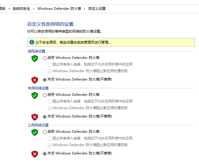
- Q: S100 cannot ping Windows, but Windows can ping S100?
- A: Check if Windows firewall is turned off; Windows built-in firewall is shown below:
U-Boot Debugging and Upgrade
-
Q: U-Boot network auto-negotiation fails or cannot ping after negotiating to Gigabit?
-
A: Check if the network cable is Cat6. The PHY and peer might switch between 100 Mbps and Gigabit, causing a speed mismatch between MAC and PHY.
-
Q: U-Boot cannot read/write PHY?
-
A: Check if PHY is de-asserted from reset; check if the mdio address used by software matches the hardware configuration.
-
Q: U-Boot upgrade fails (cannot ping)?
-
A: Check IP configuration, serverip; use a small LAN or direct connection to PC. Check MAC configuration; verify that the expected NIC is being used. Check if the network cable is Cat6.